RECAP ON FUSION 360 (CAD)
The first lesson of the module is the recap on Computer-Aided Design (CAD) using Fusion 360. It is something I am not totally unfamiliar with as I actually learned how to use this last semester. However, I have not touched it for quite a while so the recap is a good revision to familiarise myself with the software again.
Let's Recap...
What is Computer-Aided Design? It is basically how the computer help to engineer and design various projects. (What is Computer-Aided Design (CAD)? - Definition from Techopedia, 2021). Fusion 360 is computer software that is capable of CAD. To revise what I have learned last semester, I did a tutorial on keychain design using Fusion 360. Next, I will be sharing how it is done in clear steps.
Instructions on how to Design a Keychain
By following the below simple steps, you can also make a keychain of your own.

Step 1: Click the "create a sketch" button
Step 2: Draw a rectangle (65mm x 25mm)

Step 3: Select the "offset" button
Step 4: Click on the rectangle and offset it by 2mm

Step 5: Select the "fillet" button
Step 6: Click on the 4 outer corners and type 5mm for radius

Step 7: Select the "line" button
Step 8: Create a vertical line along here. Right-click the line and press "Normal/Construction". (solid line becomes dotted line)

Step 9: Select the "dimension" button
Step 10: Click on the vertical line inserted earlier and the outermost line on the left. Then, type 7mm distance between them

Step 11: Select the "sketch point" after clicking the "create" button
Step 12: Create a point in the middle of the line

Step 13: Select "center diameter circle" after clicking the "create" button
Step 14: Draw a circle with 5mm diameter from the point created just now

Step 15: Select "text" after clicking the "create" button
Step 16: Select "Impact" as the font type and type your name then adjust the height such that it fit the rectangle.
Step 17: Press the "FINISH SKETCH" button

Step 18: Select "extrude" after clicking the "create" button
Step 19: Select the base to extrude and type 3mm. Exclude the hole

After extruding, you will see something like the picture on the left

Step 20: Press the "eye" icon beside "bodies" to hide the browser
Step 21: Press the "arrow" beside "sketches" to show the sketch. Then, press the "eye" icon to show the sketch.

Step 22: Select "extrude" after pressing the "create" button
Step 23: Press the border and your name. Type 1.5mm

Step 24: From the extrude menu, select "offset plane" and enter 3mm

And that's how you can design a keychain using FUSION 360. Below is a 3D design of my keychain and you can rotate around to see the design.
Conclusion
I am still not very familiar with CAD software but I think this is a simple tutorial so I am able to follow the guide and design the keychain easily. I definitely need more practice on it because it will be needed to produce the prototype. By then, I won't have the exact tutorials to guide me on how to design. Hence, I think that this is a good opportunity to sharpen the CAD skills learned in the previous semester. Overall, I really enjoy designing it as I am able to see the result instantly which is really fulfilling.
WEEK 2 (Designing Handphone Stand using CAD)
Instructions on how to Design a Phone Stand using Fusion 360
For this phone stand, it was designed using parametric that can be made using laser-cutting. First of all, to make the phone stand, I need to know the dimension of my phone📱. I'm currently using the iPhone XS Max and I found its dimension online.
 |
| (Apple iPhone XS Max (12th Gen) Dimensions & Drawings | Dimensions.com, 2021) |
From the above photo, the estimated dimension📏 would be:
- Length = 158mm
- Width = 78mm
- Thickness = 8mm
This dimension will be helpful during the designing of the phone stand using parametric. Now, you can open up Fusion360 and follow the below steps to make a simple phone stand. (Press on the photos for a clearer picture)

Step 2: Press "modify" from the tabs and select "change parameters"

Step 3: Press "user parameters" and key in the details from the table one by one. An example is shown in the picture on the left

After keying in everything, you should see something like this

Step 4: Select "line" from the tabs and create a horizontal line with (1.1*P_width) mm

Step 5: Select "line" again and press on the most right point (circled in red) from the horizontal line created just now. Key in (0.5*P_Length) mm for measurement and 108º for angle

Step 6: Select "3-point arc" from the tabs and make a semicircle with 8 mm diameter. (circle in RED)
Step 7: Select "line" and make a line with (0.3*P_Length) mm measurement and (3*P_Angle)º angle. (circle in YELLOW)

Step 8: Select the "line" function again and drag it horizontally till it coincides with the base. (circle in RED)
Step 9: Select the "line" function and drag it vertically upward from the last point. (circle in YELLOW)

Step 10: Select the "offset" function and offset it by about 5mm

Step 11: Select the "line" function and connect the points circled in RED to complete the sketch
Step 12: Press "finish sketch"

Step 12: Select the "extrude" function and press on the blue figure and extrude it by (P_Width*1.2) mm

Step 13: Press on the plane outlined in RED
Step 14: Select "create sketch" function

Step 15: Select the "line" function to create the vertical lines of the figure outlined in RED
Step 16: Select "3-point arc" to create semicircles that connects the lines to complete the figure

Step 17: Select the "extrude" function and cut away the figure created in Step 16 to make a hole
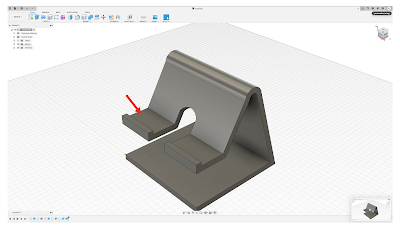
Step 18: Press on the plane directed by the RED arrow
Step 19: Select "create sketch" function

Step 20: Select the "rectangle" function and create a rectangle (circled in RED)
Step 21: Extrude the rectangle to cut it away to make a hole

Step 22: Select the plane directed by the RED arrow

Step 23: Select the "rectangle" function and create a rectangle (circled in RED)
Step 24: Extrude the rectangle created in Step 23 to make a hole
Step 25: Press on the plane directed by the GREEN arrow

Step 26: Use the "line" and "3-point arc" function to create a figure circled in RED
Step 27: Extrude the figure circled in RED to make a hole

Step 28: Extrude the figure circled in RED to make a hole
Step 29: Press on the plane directed by the RED arrow

Step 30: Select the "rectangle" function and create 4 rectangles with a length of 27mm and a breadth of 2.5mm.
Step 31: Select the "dimension" function to ensure that the distance between the two rectangles is (P_Thickness+0.5)mm

Step 32: Extrude the 4 rectangles by 3mm

Step 33: Select "fillet" and fillet and the edges of the 4 rectangles by 1mm

Step 34: Select "fillet" again and fillet and tips of the base circled in RED by 10mm

Step 35: Select "fillet" and fillet the edges circled in RED by 5mm

Step 36: Go to "modify", scroll down and select "appearance". A table will pop up. Under library, select "metallic". Colour the phone stand with SILVER followed by BLUE

And that is the way to design a phone stand with Fusion360. Since this is done using parametric design, we can actually change the parameters defined to make necessary changes so that it can be customized to another phone's dimension. Below is the 3D modelling of the phone stand designed. Feel free to rotate around to view the object. Hope you enjoy this tutorial!
Reflection
This tutorial on the phone stand is definitely a new challenge for me as I am still not very used to designing complex designs on Fusion360. However, I believe with hard work and endurance, I am able to finish this tutorial on phone stand design. It took me quite a while to actually complete this tutorial and I think I am more confident in using Fusion360. It was long but it is really fulfilling to see the end product being crafted.
Reference
- AlopezEDU (2019) Create a Keychain in Fusion 360 [online video] Available at: <https://www.youtube.com/watch?v=y2yezZKNiOo> [Accessed 21 October 2021]
- Autodesk.com.sg. 2021. Fusion 360 | Cloud Powered 3D CAD/CAM Software for Product Design | Autodesk. [online] Available at: <https://www.autodesk.com.sg/products/fusion-360/overview> [Accessed 21 October 2021].
- Dimensions.com. 2021. Apple iPhone XS Max (12th Gen) Dimensions & Drawings | Dimensions.com. [online] Available at: <https://www.dimensions.com/element/apple-iphone-xs-max> [Accessed 27 October 2021].
- Squad 5 (2021) How to make a mobile stand in fusion 360? in telugu [online video] Available at: <https://www.youtube.com/watch?v=CffhwQhYbKY> [Accessed 27 October 2021]
- Techopedia.com. 2021. What is Computer-Aided Design (CAD)? - Definition from Techopedia. [online] Available at: <https://www.techopedia.com/definition/2063/computer-aided-design-cad> [Accessed 20 October 2021].
Comments
Post a Comment