Laser Cutting
Lesson Recap on Laser Cutting...🧠🧠🧠
 |
| (Fusion M2 32/40 Technical Specifications, 2021) |
- Avoid staring into the beam while cutting
- Do not use materials that contain CHLORINE (e.g. PVC) or FOAM
- Do not cut or engrave Metal materials
- Never leave the machine unattended while cutting/engraving
- If a small fire occurs, attempt to extinguish it by blowing it or removing material from the laser cutter
- If the material cannot be cut through, STOP & CHECK, FOCUS lens might be dirty, by continuing to use the dirty lens will result in the cracked lens!
- uses pixel resolution that use colour and tone to produce an image
- file format: GIF, JPG, BMP, PNG, TIFF
- pixels appear like little squares on graph paper when the image is zoomed in or enlarged
- created by the digital camera, scanning into the computer or raster-based software
- uses scalable resolution
- file format: EPS, SVG, AI
- graphics consist of anchored dots and connected by lines and curves, similar to the connect-the-dot activities
 |
| (Raster (Bitmap) vs Vector, 2021) |
After the files are saved either in vector or raster form, it needs to be processed using CorelDraw software before it can be laser cut. To know more about how to use the CorelDraw software, please look forward to the next week blog for more detailed steps.
WEEK 4 (Laser Cutting Practical)
Improved Standard Operating Procedures (SOP) of EPILOG FUSIONPRO
Start-Up Procedures
Steps | Description |
1 | Turn on the fume extractor located at the side of the laser cutter machine by pressing the green button. 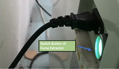 |
2 | Turn on the laser cutter machine by turning the key power switch and wait for the machine to finish the initialization. The FusionPRO laser cutter has a built-in air compressor that provides air directly to the work surface and it will be activated when the laser cutter is on.  |
3 | Proceed to the workstation and send the drawings to the laser cutter. |
Operating Procedures
Steps | Description |
1 | Open CorelDraw and click on Files>New  |
2 | Import DXF file or SVG file or create your own design in CorelDraw. Click ‘Ok’ to import. |
3 | The shapes that were in the file will show up. Click on the lines or the area to fill. |
4 | Use RGB colour. Change the colour G to 255 with no hairline for engraving. Change R to 255 with hairline for vector cut.   |
5 | For engraving, change fill colour to green. For vector cut, fill colour remains as no fill. |
6 | After setting the line weigh, colour and fill depending on your needs, click on File>Print, press print.  |
7 | Press auto focus to thickness which is on the top right of the screen.  |
8 | Open material library which is at the top right of the screen. |
9 | Select the material and its thickness.  |
10 | Select 300DPI option which corresponds to your material. |
11 | If the material thickness at the material library do not have the same thickness as the actual material, you change the thickness manually. |
12 | Carefully raise the cover of the laser cutter machine, place the material into the printer, and adjust the sketch on the EPILOG dashboard. |
13 | Click Print. |
14 | Check your file name and estimated time to cut on the LCD Touch screen.  |
15 | Once confirmed, press “GO” button to begin cutting/engraving.  |
16 | Observe the laser cutter throughout the cutting/ engraving process to ensure that no flame. |
17 | Once the cutting or engraving has completed, wait for 1 minute with the lid closed and the LEV unit running. Then, open the lid and remove the finished pieces from the bed. |
Shut-Down Procedures
Steps | Description |
1 | Clean the tray where the small pieces of waste material may fall through. Also, remove the larger pieces of waste materials and discard them into bins. |
2 | Close the lid of the laser cutter. |
3 | Turn off the key power switch of the main laser cutter, followed by turning off the fume extractor button in green. |
Individual Competency Test
 |
| Wooden Square Block |
Parametric Construction Kit
Stage 1: Ideation & Deciding on the Measurement of Parametric Kit |
 At Stage 1: After ideation, our team decided to make a parametric construction kit on the Balance Scale. We first sketched out the necessary components needed to come out with a balance scale as the photo above. However, the difficult part was not designing the balance scale. Rather, it is about deciding on the measurement of the balance scale. We were not sure how huge is it supposed to be or how the kerf measurement is to be determined. Indeed, we spent a lot of time deciding on the measurement. The above photo is just a rough calculated estimation of the measurement and had yet to be finalized then. At this stage, we realized the importance of the parametric design function on Fusion360 because it allows us to determine the measurement later when the sketches have been created. |
Stage 2: Setting up Parameters Fusion360 |
 At Stage 2: We reached the point where we needed to transfer our ideas into Fusion360. First, we needed to define the parameters on Fusion360. Due to many components of the Balance Scale, a lot of parametric names had been used as shown in the above photo. To have easier sketching, we clustered the parts where they should have the same measurement and design. The expression for the parametric is first decided based on the rough estimation made in Stage 1. |
Stage 3: Sketching Components on Fusion360 |
 At Stage 3: The sketching of the components was done based on the ideas ideated in Stage 1. This was where we made use of the parameters defined in Stage 2 to aid in our sketches. Even though parametric design did help with the sketching, there were still some problems encountered. Some of the problems arose were: “How do I make sure that the measurements are aligned?”, “Will the construction kit connect together with this measurement?”. It is inevitable these kinds of problems will arise because we were unable to touch, see and connect it at this stage. We tried to tackle the problem even though we know that it may not be successful when it’s cut out. The only thing we could do was to trust the calculation at this stage. We calculated how long should the gap be, how far should the kerf be placed from the base/side. The calculation is reflected in the sketches we created above. |
Stage 4: Using Fusion360 to simulate how the Construction will turn out | |
 | |
Top View | Bottom View
|
 |
 |
Front View | Side View
|
 |
 |
At Stage 4: A simulation of how the Balance Scale. After all the sketches are done, extrude function is used to make each part of the scale thicker. The thickness used was 5mm hence we must ensure that all our connectors have at least 5mm leeway so each piece can connect to one another. After we extruded out the sketches, each piece was put together one by one to form the scale, starting from the base to the leaver. Each piece was manually placed by using the move function. One of the hard parts was to put all the pieces together. It is extremely difficult to put piece by piece at an exact location with minimal error. If it is put too off to the sides, the piece will just ‘sink’ into another piece, leaving a hole on the other side whenever we connect the pieces, thus it won’t be shown as a perfect fit. Hence, when combining each part, it was done meticulously. | |
Below show the 3D version of the Balance Scale done on Fusion360.
Stage 5: Using CorelDraw for Laser Cutting |
 At Stage 5: The sketches from Stage 3 were exported as DXF file to be imported into CorelDraw for laser cutting. On the CorelDraw, some of the set up were needed to be done before sending the file to the laser cutter for cutting. After the DXF files had been imported into CorelDraw, vector, hairline with red RGB 255 outline is set up to all the sketches. This is because we were only using the cutting function, so vector is used. Then, the file is ready to print but before that, plywood wood is chosen as the material to cut out the sketches. After that, the file was sent to the laser cutter for printing. The experience of using the laser cutter went smoothly and this is mainly because our team had passed the individual competency test, so we know how to operate the laser cutter. However, we didn’t manage to laser cut all of our components due to lack of time. Nevertheless, we managed to cut out the main components in which the structure of the Balance Scale can be seen (refer to photo above). After the cutting was done, we tried to piece the components together, but problems arose. The bottom joint hole was a bit loose as the width is slightly larger, so the balance scale is unable to stand straight. We wanted the joint to make it just right, so we changed our parametric measurement on Fusion360 to make the width shorter. However, we ran out of time, so we didn’t manage to laser cut the new measurement. Instead, we decided to do some modifications to the Balance Scale to make it work. |
Stage 6: Modification to Make Construction Work |
 At Stage 6: Our objective is to make the Balance Scale work, but we had no more access to the laser cutter, so we made use of a hot glue gun to stick the components together to make it stand. On top of using a hot glue gun, the Base had a missing hole to connect to the Scale, so we made another hole using a pen knife to connect it to the Scale. As for the Pan Holder which we didn’t manage to laser cut due to lack of time, we decided to use common materials that can be found at home to make the Pan Holder. We decided to cut out the plastic cup into a short cylinder shape with an opened top to make the Pan Holder. Then, we used the thread to hook the Pan Holders along with the pivot. The photo above is the final product of our construction kit. |
Reflection on Laser-Cutting Experience
Reference
- Epiloglaser.com. 2021. Fusion M2 32/40 Technical Specifications. [online] Available at: <https://www.epiloglaser.com/laser-machines/fusionm2-techspecs.htm> [Accessed 27 October 2021].
- Vector-conversions.com. 2021. Raster (Bitmap) vs Vector. [online] Available at: <http://vector-conversions.com/vectorizing/raster_vs_vector.html> [Accessed 27 October 2021].
Comments
Post a Comment